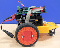
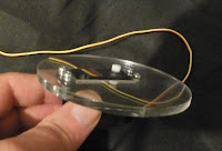
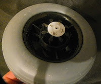
Any regular reader of this blog will know that I regularly order components from China. People have told me that they wouldn't do that mainly because of the distance and the language barrier. The delay in receiving the goods is also a factor for many. I have always taken a more pragmatic view of the situation. The particular goods I buy are, in the main, only available from these suppliers and are certainly much cheaper. Over the past year or so, the delay in receiving my parcels has increased due to customs activity in Hong Kong as it seems all the post is routed through that bottle neck now.Whilst I have never been let down by a Chinese supplier, the quality of service is variable. Recently, however, I have begun buying from Chip Partner and they have cracked the whole market wide open. They have most of the items that the other suppliers have and usually match prices very well. The best part, however, is their communications. They really go the extra mile when it comes to letting the customer know what is happening with their order. If you want to dip your toe in the water of buying from China, I suggest making them your first point of call.
Tuesday, December 17, 2013
Monday, November 18, 2013
And a bit more...............................
 The voltmeters I ordered from China have just arrived and they are lovely little toys. Very small, not much bigger than the display alone, and only two wire connection. They operate on any voltage from 2.5V to 30V and just work. They cost me 99 pence each and are brilliant. I intend to couple them with one of my homebrew mains power supplies and a DC-DC converter to make up some very useful variable power boxes for my various projects.
Monday, November 4, 2013
PIRfec'
 As pop Larkin never said. The board arrived on Saturday and I cobbled together a quick test that very evening. It worked first time. Now I want to build a small unit to mount above the bedroom door to switch on a couple of LEDs to light our way to the bathroom at night. I will document.
This is a very small item and costs very little. I bought one for £2.54 and it's possible to buy a pack of ten from China for even less per item. Just check out eBay.
What is it? It's a very small PIR (infra red motion detector) that interfaces directly to an Arduino and can trigger an action. In this instance, I want it to turn on a couple of white LEDs for a short period.
What is it? It's a very small PIR (infra red motion detector) that interfaces directly to an Arduino and can trigger an action. In this instance, I want it to turn on a couple of white LEDs for a short period.
Saturday, October 26, 2013
Oh, the excitement!
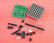
When the power boards arrived yesterday, I began a search for a proprietary method of connecting LEDs to the Arduino as I have a use for the MAX7219 chips I recently bought. After a bit I discovered the ideal solution from the same supplier. Not only is there a board, there is a complete dot matrix display in component form. They have single units to bid on and packs of four for a fixed price. This is the fixed price option here and there are auctions currently for just one.

And another thing.........................
I have received only one comment about the new layout so far, Ian suggested a slightly bigger and thicker font as he is having a little difficulty reading the previous one due to age related eyesight issues. So I have opened up the font a bit and made it bold.
Thursday, October 24, 2013
Power supplies, again.
Anyone who has read this blog on a regular basis will know that I have been working on producing some suitable power supplies for my projects. I have been successful but at a cost. The cost mainly being in my time and the size issues of some of the components. So I have been looking out for a cheaper alternative for some time. I found a very nice looking board with almost the exact specifications and handling as the ones I was building in the Cool Components listings but they sold out as soon as the new stock arrived due, probably, to the very good price. So I widened my net and found a slightly different model for a somewhat higher price and bought a couple of them. Very nice quality but larger than I was looking for. So I kept looking and finally found the original boards on sale from a Chinese supplier for an even cheaper price as long as I bought at least three at a time. I took the plunge and ordered six. The Hong Kong Post Office caused a delay in delivery by a change in their procedure, they now x-ray everything leaving the country, but the supplier, Chip Partner, kept me informed and the goodies finally arrived yesterday. So here they are,
Tuesday, October 15, 2013
Next move......
I have now widened the template and altered a few minor items, there may well be more to follow but please let me know via a comment if you like or dislike any changes.
Thursday, October 10, 2013
Changes in the pipeline
Several changes will be happening to this blog in the next few months. The first is the change of name as now seen above. The old name changed when I moved on from just Arduino to Raspberry Pi as well. Now I am also taking an interest in the Cubieboard I decided that just adding the new product to the name was a board too far. So, after a moment of epiphany yesterday evening, we now have the name of Tech That!. I won't apologize for the pun as I have loved them all my life and this was just the opportunity I was looking for to insert another one into my life. The second change should happen soon, the old icon will disappear and a new one will arrive. This is only a stopgap until I am able to think of something more suitable than a caricature of me. The third change I would like to make is a bit more fundamental, as I know that a lot of people who read this blog don't have a modern widescreen monitor. Since it's beginnings, this blog has always catered for standard screen monitors. However, with such a lot of new information available, I would like to make use of a different template in order to maximize how much can be seen without scrolling down. If you have any strong concerns about this please contact me as I would like to take this step with your agreement.
So, to restate the obvious, this blog now covers Arduino, Raspberry Pi and Cubieboard products and may well also take on other home and educational products as time passes. As an example, I am currently playing with EL wire and hope to be able to interface it with an Arduino in order to produce a copy of a neon sign.
As always, if you would like to contribute to this site please email me and we can work it out.
| English: Diagram of electroluminescent wire (Photo credit: Wikipedia) |
| Close up of El-Wire of a variety of colors (Photo credit: Wikipedia) |
Wednesday, July 17, 2013
Comin' up to speed again...............
It's been a while and I'm sorry for that but life has been..............complicated for the past few months. I'm hoping that it might return to normality now. Since my post about the Cubieboard, I have played with it a bit and begun to realise it's potential. In the same way that the Raspberry Pi will never replace an Arduino, the Cubieboard will never replace the Raspberry Pi. They are different animals and have very different capabilities. I have spent a couple of days playing with some Adafruit Flora RGB LEDs and most impressive they are. In addition, the software is so easy to write for very clever results. I am also currently playing with some EL Wire on Sally's behalf with some thoughts to making an illuminated logo for her.
Tuesday, June 18, 2013
And now.........The Cubieboard!
I have been away for a while and then began a painful interlude with my back. I am, however, mostly back to the task in hand. I found, by a very strange route, a new board that seemed to promise more than anything else yet tried. So I bought one. The supplier is Cool Components and The Cubieboard is the board. It is small, well made, inexpensive and very powerful for the price. It arrives with Android 4.1.1 pre-installed and runs straight out of the box. Imagine a Raspberry Pi that is capable of almost everything that a smaller PC can do and you have the right idea.
Yes, that is a sata connection you can see. What you cannot see is that this board also has a line in and headphone out capability as well. Click on the photo to take a closer look.
Wednesday, May 1, 2013
It's late, and I'm very tired, but........................
I finally persuaded my sketch to run correctly. I now have my two TagBot 3s reacting to obstacles and 'bouncing' when they can't move forward. I'm using the new type of IR detector that simply outputs HIGH when it detects something at a pre-set distance. Coupled with the Hub-ee wheels,this is a very self contained and simple mechanical set up and the script becomes almost as simple too. The basic sketch is as below, the various movements are in functions (forward and bounceL in this instance). Now I have the basic system working to my satisfaction, I will begin to refine the functions first and the loop next. It goes without saying that the sketch at present is very crude and not much more than a proof of method but I would ask you to remember that I am teaching myself this language as I go from books that don't always explain what I need to have explained so I am working on a hit and miss method of writing my code. Nonetheless,I am learning!
#include <HUBeeBMDWheel.h>
HUBeeBMDWheel leftWheel;
HUBeeBMDWheel rightWheel;
int leftSpeed = 0, rightSpeed = 0;
int outputPin = 7;
int inputPin = 4;
int val = HIGH;
void setup()
{
pinMode(outputPin,OUTPUT);
pinMode(inputPin,INPUT);
leftWheel.setupPins(8,11,9);
rightWheel.setupPins(12,13,10);
leftWheel.setDirectionMode(1);
rightWheel.setDirectionMode(0);
}
void loop()
{
val = digitalRead(inputPin);
digitalWrite(outputPin,val);
if (val =HIGH)
{
forward();
}
else (val = LOW);
bounceL();
}
void forward()
{
leftWheel.setMotorPower(150);
rightWheel.setMotorPower(150);
delay(5000);
leftWheel.setMotorPower(0);
rightWheel.setMotorPower(0);
}
void bounceL()
{
leftWheel.setMotorPower(-50);
rightWheel.setMotorPower(-50);
delay(2500);
leftWheel.setMotorPower(-50);
rightWheel.setMotorPower(50);
delay(2500);
leftWheel.setMotorPower(0);
rightWheel.setMotorPower(0);
}
If you have got this far and understand what I am doing, you will also have noticed that there is at least one line of code here that is unnecessary. It's a hang over from some earlier testing and will be removed before I produce the next version.
Thursday, April 25, 2013
The lovechild of an alliance between Arduino and Pi?
That got your attention didn't it?

In fact, the item I am writing about is pretty much that thing. It's also very small, in fact it's Teensy. It's available from Cool Components and it's called the Teensy 3.0 board. An ARM chip with some very nice capabilities but also capable of running Arduino IDE produced software.
Go and have a look at the specifications and then look at the price and you will see why I'm getting enthusiastic about it. Always remember, however, that Cool Components price everything at net price so you will need to add your local VAT or equivalent to the quoted price of £16.71.
This months PC Pro (UK edition) has quite a spread on the Arduino platform with a project based on the Leonardo. It may even have helped me to solve a problem I am having with an 'if----else' loop.
Friday, April 12, 2013
Function this!
Sometimes, you get so far in a project that you know, instinctively, that now is the time to stop and leave it because if you move on right away you will spoil something. I have had several momentary flashes of inspiration like this with my TagBots and yesterday evening was the latest blinding flash of understanding. I was very keen to investigate how functions operate on the Arduino so I started playing around with some simple ones related to the wheels on TagBot 3 and, after a few minor glitches, I managed to make a suite of functions work from within a loop. That was when I stopped and went quietly to bed. Tonight, I will be looking deeper into the Hub-ee library to see if I can use it for even more accurate movement.
As an aside, yesterday I had to charge up my LiPo battery for the first time. I was astonished at how quickly it came back up to full power even on the standard charge setting. If I have one recommendation to pass on, it is this; invest in a good charger, I have a B6AC unit, and good LiPo batteries and forget all about any other type of portable power. They weigh very little and do so much. The batteries are reasonably priced, smaller and, with a good charger, very easy to use.
I can also report, with the greatest pleasure, that the Creative Robotics shop is now open for business. For a short time it will be for UK customers only but, once thoroughly tested, it will be opened up to the rest of the world. I have changed the links as appropriate on the side panels, shop on the left and main site on the right.
The shop name is slightly different to the main company, Createbots. They are not just selling the Hub-ee wheels, they also have the rest of the related products and some bits and pieces for Arduino users.
Thursday, April 11, 2013
Presenting, TagBot 3
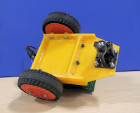
 TagBot 3 is a much more stable platform than TagBot 1, due mainly to the slightly larger base size and the horizontal mounting of the Arduino and shield. That has also helped to make for a tidier appearance as I was able to tuck the battery away under the boards. The chassis is, once again, 3mm thick, laser cut and stuck together with solvent. This time, however, I have also strengthened some of the joints with hot glue and that has made a big improvement to the stability of the side panels. The wheels are mounted using a pair of laser cut washers of the same thickness as the chassis panels in order to keep the moving parts away from the chassis itself. This also has the added advantage of letting the plug on the wheels sit very snugly between the wheel and the chassis with no chance of it pulling out. The mounting bolts for the wheels are too long on this version as I ran out of the slightly shorter ones I used previously so I have used 30mm bolts as a temporary fix until pay day.
The view from the rear shows the battery under the boards and the ball jockey in it's tallest build to balance up the chassis.
A word of warning, the spurious wires you can see in most of the pictures are not part of this tagbot. They are a hangover from another test setup that used a 315 MHz remote control system. The TagBots have now outgrown that as I am moving into the area of Bluetooth control instead. Unfortunately, I can think of no way to remove the stuck on board without damaging either or, more probably, both so it has to stay. Note to self, "Get two more shields".
The final icing on the cake is this video of Tagbot 3 running through some very basic commands in order to test stability. It's not very long and was made mainly for my benefit so I have simply added some titles and information to it and pushed it straight to YouTube.
Wednesday, April 10, 2013
All good stuff
as a good friend used to say.
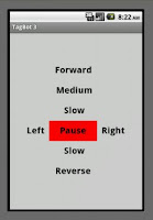
I have now built a TagBot 3 chassis and fitted the electronics to it. Photos will follow soon but, just as a warning, I have named it, "Yellow Peril". I am also now writing my own Android app to control the beast as the various apps I have already tried all seem to be either too simple or too complicated for my needs. My app is just a set of buttons that send a letter to the 'bot by Bluetooth, all the work is then done by the Arduino. Here is a sneak preview of build 1.0
I have, by writing the app in this way, a simpler method of decoding the instructions at the 'bot and outputting to the wheels. We shall see.
Tuesday, April 9, 2013
Breaking News.............................
Not really, it just looks good.
I subscribe to many feeds and blogs related to Arduino and Raspi stuff and every so often I see something I feel the need to share with others. Today was my YouTube rollup day and this immediately caught my eye. The Magpie is a simple concept, pin 13 has an LED on all Arduinos. The Magpie has an LED on every pin. Debugging sketches would be just so easy with one of these as you would always be aware of the state of the outputs.
Monday, April 8, 2013
And orft we jolly well.................
I have, at last, got around to designing the next Tagbot chassis. I was originally intending to build the second version with a vertical board in the same manner as the first but when I began playing around with the measurements derived from the first chassis, I realised that it would be easier to jump straight to TagBot 3 than try to make TagBot 2 work better than TagBot 1. So there it is, I will, hopefully, be building the new chassis quite soon and then I will have something to run the new software on. I am still having trouble with the Bluetooth connection, I can make it work but not using my parameters. This is proving a major problem and I need to get on with it soon.
Anyway, the new chassis holds the boards horizontally and is slightly wider and a bit longer to accommodate both the boards and the battery pack. The width will also help with the Hub-ee cables as well. On chassis 1, they fitted more by good luck than good planning. The moral being, of course, that we live and learn.
Tuesday, April 2, 2013
Oh Calamity!
Major inclined plane helical object rising vertically!
I managed to solder in the wrong size of pins on one side of the second shield over the weekend. Removing them was less than easy despite having the correct tools so I now have a damaged shield. I will buy another but, in the meantime, I am reliant on the original shield. So I have disconnected the 315 Mhz board and connected the new Bluetooth board to the Arduino. This all works really well apart from the code I have written. I am obviously making a very big, but probably simple, mistake in the way I am trying to implement the 'switch / case / break' method on my sketch. The sketch I wrote compiles but it just won't do anything when sent to the receiver. The receiver pairs with my phone ok but there seems to be no understanding from the Arduino end. Bah!
Thursday, March 28, 2013
ooops!
I should have checked before I ordered them, the WiFi cards are not compatible with the new shields. Only me to blame, I just didn't bother to check. Now I have checked a pair of Bluetooth boards and they are compatible so I have ordered them. The other advantage with Bluetooth is that I will be able to use my phone to control the 'bot and won't need to build a special controller. If you want to know how, check out BTInterface. It's currently a free beta app but it seems to work very well and I suspect it may become a paid for app quite soon. In addition, I have also learned how to interface the cards with a Raspberry Pi and that opens up more opportunities as well. I am now looking forward to TagBot 5 which if all goes to plan will incorporate an Arduino acting as a slave to a Pi which is connecting with a controller and sending back real time video from a pan and tilt unit as well. Well, I can dream............
Tuesday, March 26, 2013
Constructive criticism
is alive and well and working hard at the moment.

Build 1 is up and running. However, it falls over a lot due to the wheels being set too high on the chassis. The wheels also have a slight tendency to fall off if treated roughly because of the mistake I made with the cutting of the base panel. Whatever, the remote control is fitted and, although a bit rough and ready, is also working well enough to be a proof of viability. I am using a very simple 315Mhtz transmitter/receiver set up because of the ease of interfacing to the Arduino and also that the size just fits the shield. A closer look at the front view will explain how the two boards are fitted together. The new shield from Creative Robotics is, as is usual, plugged into the Arduino. In this instance, a Duemilanove is used due to cost and size considerations. The receiver board is stuck to the central prototyping area of the shield with hot glue and hard wired into the power and ports used. (Please note, not the ports you can see in the photo as I have changed two of them for a simpler software option whilst testing.) The wiring for the wheels has been carefully twisted to avoid the wheels themselves due to the small gap between the wheel and board on this build. For anyone contemplating a robot of this type, I would offer some advice based on what this first build has taught me, leave more space between the wheels than this - at least an extra 10mm on each side - extend the base board to at least the height of the vertical panel - in this instance 90mm - and make sure the wheels and the ball at the rear are at the same height as, though amusing to watch the first couple of times, the sight of your little robot falling over can get annoying after a short while.
Advice for the longer term would be to use one of the new Arduino Due boards for all sorts of reasons and, for the greatest stability, a four wheeler with servo steering. My next build will still be a two wheeler, although with most of the improvements mentioned and a wifi card instead of the 315Mhtz system. I will talk about my software in a later post as the current version is very crude and simply makes the robot work for test purposes.
Saturday, March 23, 2013
Let's go!
Well,nearly.
Thanks to another Bob, I was able to build a Tagbot chassis this weekend after all. I am calling it build 1 as several minor mistakes have already surfaced. Firstly, it's just a bit smaller than it needs to be and, secondly, I made one critical part just 3mm too short. It doesn't stop it from working but doesn't look as good as it should. Nonetheless, I have put the first model together and it works. The balance is correct and the remote control module fits where I hoped it would. The battery pack doesn't go where it was intended to but that can be fixed in build 2 so, all in all, a successful first effort. Now I will begin working on the first sketch.
Wish me luck.
Wish me luck.
Thursday, March 21, 2013
Tony Blair, eat your heart out!
Things have only got better.
I managed, thanks Bill, to get hold of a couple of those new boards from Creative Robotics. As I suspected, they do exactly the job I need them to do for the new Tagbots. I built one this evening, plugged it into a Duemilanove set to the Uno version of the test sketch and off she ran. Not literally yet, sadly, as the plastic sheet has yet to arrive and I still have to get it cut on the laser cutter. I had originally hoped to have at least one Tagbot mobile by the end of the weekend but I don't see that happening now.
This is the final design for two chassis to be cut from 3mm thick acrylic sheet. When the first pair have been built to my satisfaction, I will make the actual SolidWorks files available on the code site so that anyone who feels rash enough will be able to cut them.
This is the final design for two chassis to be cut from 3mm thick acrylic sheet. When the first pair have been built to my satisfaction, I will make the actual SolidWorks files available on the code site so that anyone who feels rash enough will be able to cut them.
Tuesday, March 19, 2013
Building on my plans
comes this shield from Creative Robotics. Full details are at this URL but this is what it looks like. It allows you to connect two Hub-ee wheels to an Aduino and even access the feedback from the readers. In addition, it also has servo connections so that a pan and tilt camera or maybe an ultrasonic scanner could be run from the same board. As far as I can tell, this board isn't yet available from the distributors.
On a completely separate thought, we have finally discovered what is causing my problems with the laser cutter software. The original files are being produced at the correct size but by the time they get to the cutter software, they are so heavily reduced in size that the software can't see some of the lines and holes. We are still working on a fix.
Thursday, March 14, 2013
Old apps for new!
We may have now cracked the problems with the DXF files for the laser cutter. It seems that by making sure that the files were set to the latest version, I may have caused the problem myself. Our laser cutter has a very old application and my colleague Lee sends the oldest version of the files he is able to in order for them to work. The moral is, I suppose, that new isn't necessarily the best - sometimes old is.
Wednesday, March 13, 2013
Wha?......................
I am still having problems with my DXF files. They open fine in SolidWorks and DraughtSite but not in the special software used for the laser cutter. All the circles and vertical cuts are missing still. I have no idea what's going on.
Monday, March 11, 2013
Always check the date!
Over the weekend, in the free version of SketchUp, I re-drew the TagBot and Micro Pan and Tilt cutting plans. The results when I opened it in the Pro version looked great and I then exported a DXF file from it. Next, down to the laser cutter to check the export quality. Oh dear, not good at all. Over half the lines missing and all the circles. Went away with head bowed and tried to fathom exactly what I had done wrong. Eventually, I discovered that my copy of Pro had somehow defaulted to version 14. The current version is 2013 which is about six iterations later. I only had version 2010 available to me but I tried it and it's close enough for jazz so the files and some card have been left for a test cut. Once I have measured the test cuts against the actual hardware, I will order the acrylic sheets and get them cut ready for assembly.
Friday, March 8, 2013
Gotcha!
I have played with so many 2D CAD applications over the past couple of weeks that my eyes and brain stopped coordinating for a while. However, I have finally found nirvana. The pro version of SketchUp 8 is magic to learn and use and also exports the .DXF files needed for the laser cutter. I had used the free version of SketchUp before so maybe it wasn't such a big learning curve as it might have been but within about twenty minutes I had created a fully scaled cutting plan with all dimensions scaled. This is still not the definitive plan as I have not got the measurements of the wheels with me to copy across to the plans as yet. Once again, I am very lucky in working for a university as we have a site licence on SketchUp Pro. The cost of the personal licence, unfortunately, is quite high at £322.00. There are many cheaper options for educational use however.
Monday, March 4, 2013
Forget you? Me? Never!
Or something like that anyway.
I have been exceptionally busy over the last few weeks and I'm afraid this blog has suffered a bit. The Hub-ee wheels arrived and they are terrific. I have worked my way through various pieces of software to design for the laser cutter and I am now checking out SolidWorks. This is fine for me as I work in a university that uses the program and I was able to get a legal copy with licence. Sadly, this will only work until I retire next year so I am still investigating other methods of producing cutting plans for laser cutting. In the meantime, I have taken, and passed, an important exam and been to a wedding reception in the National Marine Aquarium. My life is busy and I will have to find more time for robotics.
Friday, February 22, 2013
Putting my money where my mouth is.
I have just ordered four Hub-ee powered wheels and matching cables from Cool Components. Well, I urged everybody else to do it so I thought I would get in on it too. My thoughts revolve around two scenarios, I can build a four wheel drive vehicle or two two wheel drive ones with a ball caster for balance. So I ordered the ball castor pack as well. I am also currently evaluating some free software, Draughtsight, to see how easy it is to design panels for laser cutting on. I know it will do the job but it also needs to be fairly easy to get accurate drawings as well. We shall see.
Thursday, February 14, 2013
Worth a look
On a more personal and immediate note, I have now moved the printer and workstation around in readiness for the rest of the work on the bench.
Tuesday, February 12, 2013
A clear working area!
For the first time since it was set up, my electronic working area on the bench is clear and all the components have gone into the racked bins, phew! The amount of space I have made is enough to enable me to begin the re-adjustment of all the areas on the bench and finally put computers and network kit in the various places originally assigned for them. The printer will be moving to the centre of the bench and my workstation to the right of it. The bench Raspberry Pi between the workstation and the electronics area and a space on the other side of the printer for working on the other PCs as and when. The network kit will go at the far end and take up as little space as possible.
At that point, I will sort out the things under the bench and, hopefully, make room for some more boxes to go under it. Then comes the main area of floor in the whole attic............................
Sunday, February 10, 2013
A slight digression..............
I've been threatening this for months, I have now mounted my trays on the alcove and have just been busy doing some labels for the top half. I finally have a place for everything, now all I need to do is put everything in it's place! I've had a busy weekend, on Saturday I finished the new mains board for my soldering irons and on Friday, I replaced the 2 mm screws with the correct 4 mm screws on the hubs They are now very solidly fixed.
Thursday, February 7, 2013
Woo hoo, again, woo hoo!
The test bed wireless remote control set arrived yesterday and, after setting it all up on a breadboard, it worked as hoped for first time. It's a digital, four channel system with a PCB receiver and a key fob transmitter. I was able to light four LEDs by pressing their respective buttons on the transmitter, that was very cool. Next is to set up the Arduino and interface the driver shield and the receiver to it.
Tuesday, February 5, 2013
Solvent Sticks
Well, the hubs are now completed and fit the main body really well. It didn't take very long to assemble and stick them together and then I assembled the whole mechanical side of the Trundle 2 for the first time. I know I'm biased but it looks terrific and balances really well. Next job is to load the continuous rotation sketch onto a Duemilanove and try a simple run.
This is a completed hub. The reason for building them this way is to produce a modular system for test purposes (initially) and so be able to swap drive systems and bodies around.
One view of the completed Trundle assembly. The body is, as yet, just a tube with no additional holes or parts added. In time I may insert a shelf so that the battery can sit in the lower part and the electronics in the upper. Also, there may be holes cut for sensors or parts mounted on the outside of the tube. A new set of hubs might have a motor drive rather than a servo. By using different hubs and bodies, the system becomes a 'Mix and Match' concept.
Behold, the Trundle Mk2.
Saturday, February 2, 2013
More beer, more beer!!
A cry from my past.
As I said, I did check whether the drive would be affected if I cut down the depth of servo on the outside of the hub. It doesn't, so that's the way I have assembled them .As you will see in the first picture, it makes the servo almost a flush fit with the 5 mm thick disc. A certain amount of jiggling is required to make sure that the body of the servo is on the same level as the disc but it's well worth that extra effort.
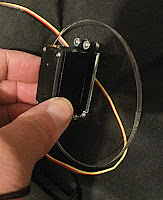

This shows just how much of the servo is now on the inside of the hub as compared to the usual mounting method. The servo itself is very stable and doesn't move at all even under pressure but the wheel will always be very slightly wobbly as it will never be a perfect fit due to the the fact that its not designed to be. Since this Trundle is only intended to be a full size test bed for the software, this isn't a serious problem. The servos will provide enough motive force to move the robot but not very quickly. In a test situation, this is a better set up than running at full speed.
The white adaptor piece (from the servo kit of parts) was first stuck to the hub and then screwed through into it in order to be as secure as possible. The screws used are M2 x 2 mm and should really be longer. The holes were drilled with a pillar mounted drill press to make certain that the holes were vertical and the tiny drill bit didn't break.
Subscribe to:
Posts (Atom)
